How to Fix Tearout on a CNC Router: Bit, Toolpath, Feed
Tearout on a CNC router is wood splitting ahead of the cutting edge. Fix it with bit helix, a 0.3 to 0.5 mm finishing pass, chip load and fibre support.
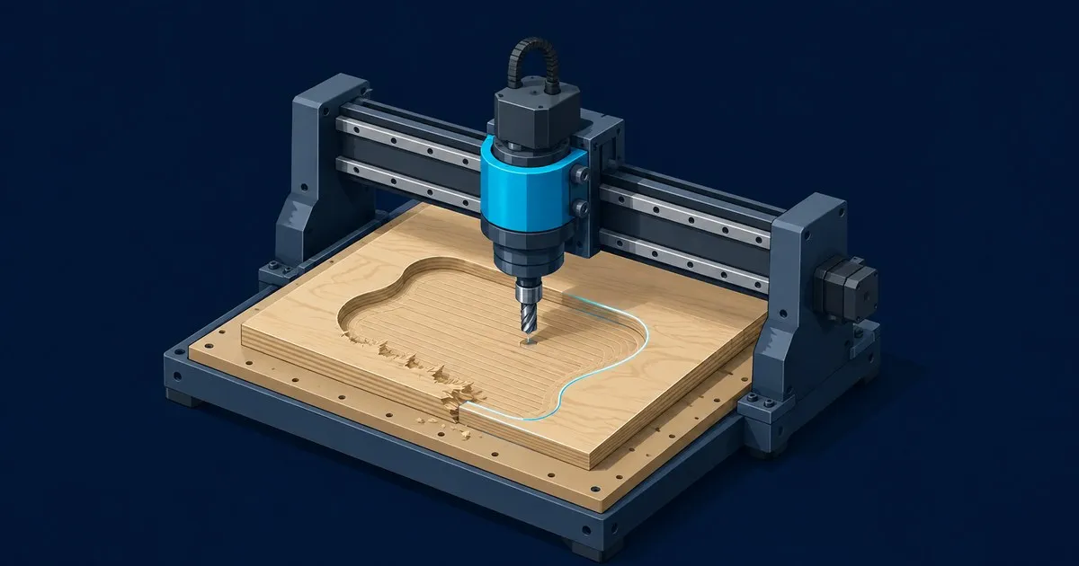
Tearout on a CNC router is three different defects: fibres left standing along the top edge, chips broken out below the line of cut on two sides of a profile, and a bottom edge that splinters as the tool breaks through. Most advice on how to fix tearout on CNC router cuts stops at “buy a downcut bit”, which fixes the first and not the other two. Below: cause and fix for each, settings for a 1/4 inch two flute spiral in Baltic birch, and a test cut to prove the change.
Read the defect first
Where the damage sits identifies the mechanism.
- Fuzz or lifted veneer along the top edge. The helix pulls fibres up faster than it severs them. Bit geometry.
- Chips below the line of cut on two opposite sides, clean on the others. The wood splits ahead of the edge where the tool runs against the grain. Chip thickness and direction.
- Splintered bottom edge, clean top. Nothing behind the last fibres. Support.
- Hairy surface everywhere, often burnt. Rubbing, not cutting: a dull cutter, or a chip so thin the tool overheats and dulls itself.
The Forest Products Laboratory’s report on torn, chipped and fuzzy grain defines chipped grain as an area “chipped or broken out below the line of cut”, attributes torn grain to “dull cutting edges and irregular grain direction”, and ties fuzzy grain to incompletely severed fibres, worse at high moisture content and in tension wood.
A USDA study of orthogonal cutting in loblolly pine (Woodson and Koch, 1970) explains the second defect: under deep cuts the wood splits ahead of the tool by cleavage, and “the amount of roughness depends upon the depth to which the cleavage runs into the wood”. Thin chips gave a clean shearing chip and an excellent surface. Dull or negative rake edges gave the chip type the authors call fuzzy grain. So the pass that defines the edge should take a thin chip, and the cutter has to be sharp.
Fix 1: match the helix to the face that matters
Sienci Labs’ cutting tool guide states the trade plainly. An upcut clears chips well but “can cause tear out at the surface”. A downcut leaves “a clean top edge but packing chips in the cut”. A compression bit gives clean edges on both faces and is the tool for plywood and laminated sheet goods, with one caveat: it must enter the path correctly, or the upcut half lifts the face veneer while the tool is still moving into position. Ramp in, and make the first pass deeper than the upcut section at the tip. Full comparison: upcut vs downcut vs compression bits.
Fix 2: leave the edge for a thin finishing pass
Tearout on two sides of a profile is cured by the toolpath, not the bit. Vectric’s 2D profile toolpath documentation describes a last pass allowance: “all but the last pass will be undercut by the specified allowance with the final pass being the only pass which cuts to size”. A reverse direction option runs that last pass the other way round, for “minimizing witness marks on the edge of profile cuts”.
ToolsToday’s plywood tearout guide puts numbers on it: rough in shallow passes, leave 0.3 to 0.5 mm (0.012 to 0.020 inch) for a full depth cleanup, and “conventional rough, climb finish often yields the crispest edge on veneers”. How each direction behaves on a flexing gantry is in climb vs conventional and stepover.
Settings, 1/4 inch two flute compression bit, 18 mm Baltic birch: conventional roughing at 3 mm step down leaving 0.4 mm on the profile, then one full depth pass with reverse direction ticked, which makes it a climb pass.
Fix 3: bring chip load into range, then back off for the finish
Freud’s feed and speed sheet gives starting chip loads for solid carbide bits at a depth of cut equal to the diameter. For 1/4 inch: hardwood 0.008 to 0.011 inch, plywood 0.006 to 0.009. It warns that “if the chip is too large, it will leave a rough surface or edge on your work piece”.
Feed is RPM x flutes x chip load, so a 1/4 inch two flute at 18,000 RPM in hardwood wants 288 to 396 inches per minute. Drop the spindle rather than the feed: at 10,000 RPM the same chip load needs 160. The chip load chart for wood covers that gap. A cut chipping at the top of the range should drop to the bottom of it for the finishing pass only.
Fix 4: support the last fibres
Bottom edge splintering and exit side blowout happen because the final fibres are unsupported. The ToolsToday guide lists the remedies: an onion skin of about 0.3 mm left on the bottom and removed by hand, sacrificial backers, tabs or vacuum against panel chatter, painter’s tape over the cut line, and a scored line to pre-sever the face fibres. On a CNC the backer is the spoilboard, which only supports work that sits flat on it.
Fix 5: sharp cutter, dry stock
The Forest Products Laboratory’s remedy for torn and chipped grain “lies mostly in keeping cutting edges in good condition”, and fuzzing grows with moisture content, particularly in ring-porous species such as the oaks. A cutter run for weeks at a fraction of the chip loads above is rubbing, not cutting. Fit a new bit before blaming the toolpath, and let stock acclimatise in the shop.
How to verify
Cut a 100 mm square through profile in scrap of the same board, grain along X. A square runs the cutter with the grain on two sides and against it on the other two.
Success: no fibres standing above the top face under a fingernail, no chips below the line of cut on the against-the-grain sides, sharp corners, and a full veneer on the bottom edge. If two sides still chip, reverse the last pass and cut again. Change one variable per test, in the order above, the discipline that makes a 3D printer calibration order hold: a fix made out of sequence is undone by the next change.
Related across the network
- How to Dry Filament: Temperatures by Material — 3dfilamentguide.com
- ansible-playbook Options: Flags That Change a Run — ansibleguide.com
- Anycubic Kobra 2 Not Extruding: Diagnosis and Fixes — anycubicguide.com
- Anycubic Photon Mono Resin Sticking to FEP: Causes and Fixes — anycubicguide.com
- Bambu AMS Troubleshooting: Error Codes, Jams & Fixes — bambureviews.com
Sources
- Forest Products Laboratory Report 2044: Raised, Loosened, Torn, Chipped, and Fuzzy Grain in Lumber
- USDA Research Paper SO-52: Tool Forces and Chip Formation in Orthogonal Cutting of Loblolly Pine
- Sienci Labs: Cutting Tools (Fundamentals)
- Vectric Documentation: 2D Profile Toolpath (VCarve Pro V12)
- ToolsToday: Avoid Tearout in Plywood
- Freud: Router Bit Feed and Speed for CNC
Related

CNC Chip Load Chart for Wood: Feeds and Speeds
Starting chip load ranges by bit diameter and material, the feed rate formula behind them, and how to correct burning, chatter and fuzzy edges.

Upcut vs Downcut vs Compression CNC Router Bits
Compare upcut, downcut and compression CNC router bits by chip evacuation, edge quality, workholding and the wood jobs each geometry suits.

How to Surface a CNC Spoilboard: Bit, Toolpath, and Settings
A source-based guide to surfacing an MDF CNC spoilboard, covering bit choice, RPM, feed rate, stepover, toolpaths, and flatness checks.