How to Surface a CNC Spoilboard: Bit, Toolpath, and Settings
A source-based guide to surfacing an MDF CNC spoilboard, covering bit choice, RPM, feed rate, stepover, toolpaths, and flatness checks.
Knowing how to surface a CNC spoilboard is the one maintenance task that quietly fixes the largest number of unrelated problems: inconsistent cut depth, parts that are thinner on one side, tabs that don’t fully cut through, and double-sided jobs that don’t register. The spoilboard (also called a wasteboard) is the sacrificial MDF or plywood layer bolted to the machine’s table, and its top face is the only surface guaranteed to be parallel to the gantry’s travel. Every Z-zero you set assumes that surface is flat. It stops being flat the moment it picks up screw holes, glue residue, humidity-driven cupping, or just wear from a hundred previous jobs, and surfacing removes a thin skim layer to true it back up.
What surfacing actually does
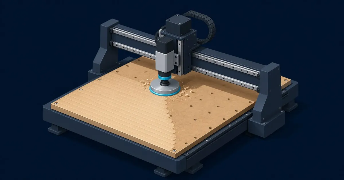
A surfacing pass is a shallow pocket cut across the entire usable table area, deep enough to remove the highest points and leave a uniform reference plane. It is not a flattening operation for warped stock sitting on the table, that’s a separate job done with the stock clamped down and only the stock surfaced. Spoilboard surfacing removes material from the sacrificial layer itself so that the table’s top face is co-planar with the machine’s XY travel to within a few thousandths of an inch across the whole bed.
Skip it and you’re not chasing a phantom problem. A spoilboard that’s 0.03” high in one corner puts your bit 0.03” deeper into the stock at Z-zero everywhere else, which shows up as burn marks on one side of a project and light, incomplete cuts on the other, even though the g-code never changed.
The underlying idea, truing a machine’s working surface so a single Z-zero holds across the whole bed, isn’t unique to routers. FDM printer owners solve the same problem from the other direction with manual bed leveling: both are periodic maintenance for a reference plane that drifts out of true with use.
Bit selection
Two bit families cover this job:
Insert spoilboard surfacing bits (sometimes called planer or surface-planer bits) are the purpose-built tool. They run 2 to 4 replaceable carbide inserts arranged with a slight dish or scoring geometry so the cutter leaves a flat, low-ridge finish instead of concentric arcs. Amana’s RC-2251 is a common 2-1/2” diameter example with two cutting flutes and two up-shear scorers, rated to 19,000 RPM max, per the vendor spec page. Larger diameters (up to roughly 3-1/2” to 4”) cover more table per pass at the cost of needing more spindle torque to keep chip load reasonable.
A single or double-flute straight or compression bit works too, just slower, because the stepover per pass is limited to the bit’s own diameter rather than a wide insert head. Sienci’s documentation notes it’s possible to flatten a wasteboard with a bit as small as 1/4”, it just takes considerably longer than a dedicated surfacing head, per their LongMill wasteboard guide.
If you’re already using a dedicated surfacing bit for chip-load reference, this site’s chip load chart for wood has the flute-count math for dialing in feed rate on a specific tool.
Settings that hold up in practice
Numbers vary with machine rigidity and spindle power, but the published starting points from router-class (non-VFD-spindle) machines cluster tightly:
- RPM: Sienci’s LongMill guide recommends the Makita/Trim router at roughly speed 3–4, about 18,000 RPM, for MDF surfacing. Insert-style bits like the Amana RC-2251/RC-2252 are rated for 18,000–19,000 RPM max, so that range is close to the ceiling on most desktop routers.
- Feed rate: 2000 mm/min (about 80 ipm) is the LongMill starting figure; higher-torque setups with a wider bit commonly run 100–200 ipm. Start at the lower end and increase until you hear the cut smooth out rather than chatter.
- Depth per pass: 1 mm (about 0.04”) or less. Sienci specifically warns that a deeper step-down with a larger-diameter bit produces an uneven surface, because the outer edge of a wide insert head is doing more work than the center at a heavy step-down.
- Stepover: Roughly 40% of bit diameter for a smooth finish, per the same guide. Note that in Vectric’s Pocket toolpath, a stepover above 50% of cutter diameter automatically triggers extra “tail” corner moves, per Vectric’s own documentation, so staying under 50% avoids relying on that cleanup behavior.
Take the first pass a little deeper only if the board is badly warped or scarred; every pass after that should be a light skim, not a hogging cut. MDF dust from surfacing is fine and plentiful, so dust collection matters more here than on most jobs, both for the extractor and for your lungs.
Generating the toolpath
The mechanics are the same regardless of CAM package: draw a rectangle sized to your full usable table (plus one bit diameter of margin on each side so the corners actually get touched), then run a pocket or area-clearance toolpath over it with no walls left standing, one shallow Z pass, and the raster or offset fill pattern set to full coverage.
In Vectric software (VCarve, Aspire), that’s the Pocket toolpath with the Raster area-clearance strategy, angled 0° or 90° depending on which axis you want the finish lines to run along. Some machine ecosystems build this in directly: Sienci’s gSender includes a Surfacing utility that generates the g-code from your table dimensions without needing a separate CAM file. Whichever tool you use, oversize the boundary rectangle past your machine’s actual travel limits deliberately, since a job cut exactly to the table’s nominal size will leave a thin unmachined strip at the edges once you account for machine flex and calibration drift.
Set Z-zero for the surfacing job off the spoilboard’s current (unsurfaced) top, not off a prior surfacing datum, and don’t touch Z again between passes. If your spoilboard is bolted down with screws, back every screw head below the deepest planned cut depth first. Insert bits shatter on contact with steel, and even a single strike can chip several inserts at once.
How to verify it worked
Run a strip test after the pass finishes: jog to Z-zero at several points across the table (all four corners and the center at minimum) and check that the bit just kisses the surface at every one, with no visible gap and no digging in. A dial indicator or even a folded sheet of paper dragged under the bit at each point is enough resolution to catch a problem; you’re checking for consistent drag, not a fixed clearance.
If one corner is still proud after a full-depth pass, don’t assume the surfacing job failed. First check gantry squareness and belt tension, since a racked gantry produces the same “high corner” symptom as an unsurfaced spoilboard and re-surfacing won’t fix it. If the table is mechanically sound, run one more light skim pass targeting only the high area before resurfacing the whole bed again.
Surfacing wears the spoilboard thinner every time, so budget for eventually replacing the sheet outright, usually after enough passes that mounting hardware starts interfering with cut depth or the board no longer has meaningful sacrificial thickness left over the T-track or clamping hardware underneath.
Sources
Related

How to Fix Tearout on a CNC Router: Bit, Toolpath, Feed
Tearout on a CNC router is wood splitting ahead of the cutting edge. Fix it with bit helix, a 0.3 to 0.5 mm finishing pass, chip load and fibre support.

Upcut vs Downcut vs Compression CNC Router Bits
Compare upcut, downcut and compression CNC router bits by chip evacuation, edge quality, workholding and the wood jobs each geometry suits.

CNC Chip Load Chart for Wood: Feeds and Speeds
Starting chip load ranges by bit diameter and material, the feed rate formula behind them, and how to correct burning, chatter and fuzzy edges.